 26Sep

An isolation transformer in UPS design provides electrical separation between specified circuits. Its value depends on where it sits, which supply paths pass through it, and what the installation needs. It is not a universal voltage regulator, noise filter, or guarantee against equipment failure.
Before selecting a UPS with isolation transformer options, define the separation required. Then trace normal operation, battery operation, static bypass, and maintenance bypass on the proposed drawing. A transformer on one path may not address a requirement on another.
This isolation transformer in UPS guide explains how to compare those choices and prepare useful questions for a supplier. It covers design review inputs, rather than wiring instructions or a site-specific grounding design.
Key takeaways
- Galvanic isolation and double conversion describe different properties.
- Input, output, and bypass transformer locations need separate assessment.
- Check the required separation in every relevant operating mode.
- Include losses, heat, inrush, space, and protection in the comparison.
- Confirm model documents and applicable requirements before changing a system.
What an isolation transformer in UPS design does
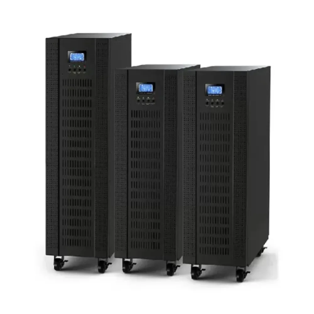
An isolation transformer transfers energy through magnetic coupling between separate primary and secondary windings. The intended electrical separation is called galvanic isolation. The complete installation still needs its own review of other connections and protective arrangements.
Riello’s galvanic isolation explanation shows that transformers can be placed at different points in single-input and dual-input UPS arrangements. Use that path-based approach when reviewing a proposal. A component label alone does not show the boundary of the separation.
Ask what problem the isolation transformer in UPS design is intended to solve. Is the requirement a defined electrical boundary, voltage conversion, a neutral arrangement, or a measured interference concern? Write the objective in the enquiry before comparing products.
Separate isolation from other functions
Double conversion describes the rectifier and inverter conversion path of an online UPS. It does not, by itself, establish a galvanic isolation barrier. Likewise, a transformer ratio does not establish automatic regulation across changing supply conditions.
For an isolation transformer in UPS proposals, separate these questions:
- Which two circuits must be electrically separated?
- Is a voltage ratio or a particular output arrangement needed?
- What disturbance has been measured, and where?
- Which operating modes must meet the requirement?
Don’t turn a need for separation into a promise that all interference disappears. Noise performance requires evidence for the relevant disturbance, frequency range, construction, and installation. A general statement about isolation is not a measured attenuation result.
Begin with the requirement. Review the available UPS systems alongside the site’s supply and load information, then request drawings for the proposed configuration. Keep the required separation visible in that request.
Isolation transformer in UPS: compare the locations
There is no single location that answers every requirement. Review an isolation transformer in UPS input, inverter/output, bypass, or downstream distribution positions against the actual circuit. The table below is a conceptual checklist, not a wiring layout.
| Proposed position | Question it raises | Document to request |
|---|---|---|
| Main input | Which UPS input circuits are supplied through it? | Main and bypass supply drawing |
| Inverter/output stage | Which output paths include the transformer? | Internal power-path diagram |
| Separate bypass input | What happens when the load uses bypass? | Bypass and transfer description |
| Common downstream position | Which upstream paths feed the downstream transformer? | Full single-line diagram, including maintenance bypass |
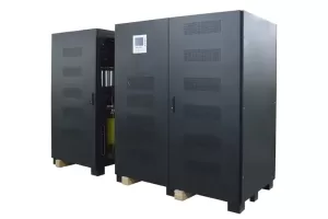
| External cabinet | What equipment and connections are included? | Cabinet scope and installation instructions |
For an isolation transformer in UPS input design, check whether a separate bypass supply avoids the transformer. For an output arrangement, check the actual connection point rather than assuming every output path includes it. Cabinet location and electrical position are not the same thing.
Illustrative scenario: two incoming supplies
A facilities team receives a proposal with a transformer on the main input. The UPS also has a separate bypass supply. The team asks the supplier to mark both routes to the load and identify whether the stated separation requirement is met in each mode.
This invented isolation transformer in UPS scenario makes no claim about a customer’s result. It shows why the second input belongs on the drawing. The existence of a main-input transformer is not enough information to approve the whole arrangement.
Preserve the distinction between design options
A transformer inside a cabinet may serve a different purpose from an external input or bypass transformer. Ask for the winding arrangement, intended function, and the model version that supports the option. Do not infer these details from a photograph.
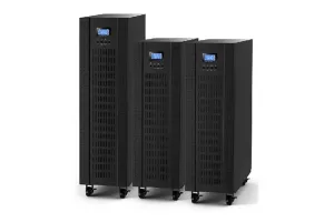
Banatton’s three-phase online UPS product listing identifies an optional isolation transformer. Request the exact option’s documentation. The listing does not prove that a particular installation already includes it or meets every separation objective.
Check normal, battery and bypass modes
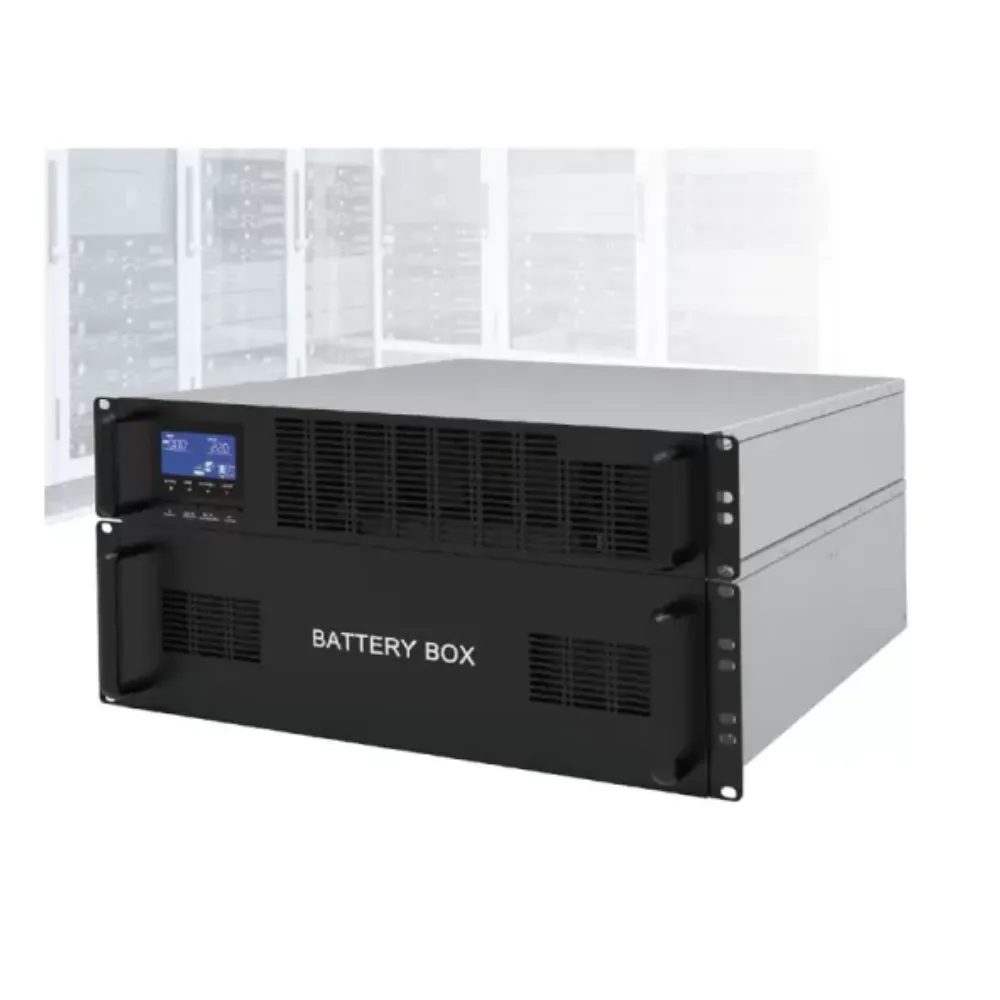
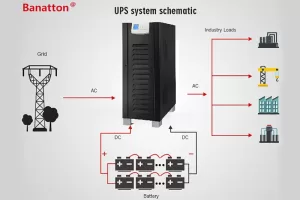
The isolation transformer in UPS review should follow each operating path. A simplified block diagram is useful, but it needs to include any external maintenance bypass and alternative sources. Otherwise, a review may miss a path used during service or a fault.
Use the following matrix to collect answers. The entries are questions, not claims that a given design provides isolation in every mode.
| Mode | Trace this path | Confirm this point |
|---|---|---|
| Normal operation | Source through the active conversion path to the load | Which transformer and other connections are involved? |
| Battery operation | Battery and inverter path to the load | Which separation boundary remains relevant? |
| Static bypass | Bypass source to the load | Does this route include the required transformer? |
| Maintenance bypass | Actual service supply route | Does it pass around or through the proposed boundary? |
| Alternative source operation | Generator or other source and transfer arrangement | Have the source and neutral conditions been reviewed? |
An isolation transformer in UPS design should therefore be assessed with the operating manual, not just a product feature list. Ask what is automatic, what is operator-controlled, and what conditions apply to each transfer. A zero-transfer claim does not establish isolation.
Illustrative scenario: a maintenance route changes the question
Assume a buyer’s requirement is to maintain a particular separation boundary during service. The supplier provides a normal-operation diagram, but no maintenance bypass drawing. The buyer requests the missing drawing before accepting that part of the proposal.
This isolation transformer in UPS example is a document-review exercise, not a recommendation to move a transformer. The designer must assess the real path, protective arrangements, and permitted maintenance procedure. No uninterrupted-service outcome is assumed.
Ask about neutral and protective arrangements
Neutral treatment, source changeover, protective earthing, and fault protection need a coordinated site-specific design. Provide the existing supply arrangement and equipment documents to the responsible designer. Do not use a general article to add a neutral-earth bond or remove a protective conductor.
When evaluating an isolation transformer in UPS service, ask which requirements apply in normal, battery, and bypass operation. Record who approves the design and which drawings define it. A generic grounding resistance figure cannot replace that review.
For input and output phase terminology, see the single-phase vs three-phase UPS guide. Phase arrangement helps describe the system; it does not establish an isolation requirement on its own.
Weigh heat, inrush, space and maintenance
An isolation transformer in UPS installations adds equipment that must be included in the overall plan. Request its losses, heat output, dimensions, mass, ventilation needs, and access requirements. Compare the complete installation rather than the UPS cabinet alone.
Riello’s 06-2020 data-center UPS white paper discusses additional transformers’ heat dissipation, startup inrush, and effects on downstream fault currents. It is a 2020 engineering reference, not a current market study or a Banatton installation specification.
Request a rating for the actual duty
For an isolation transformer in UPS input service, ask what the rating must cover under the proposed operating conditions. Include the selected UPS’s input demand and charging requirements in the review. An output or bypass position can involve a different duty.
Have the designer evaluate startup and protection coordination. Ask for the relevant inrush information and the proposed equipment’s limits. Do not assume transformer kVA must always equal UPS kVA, or apply a universal sizing multiplier from an unrelated model manual.
Adding a transformer does not automatically increase the UPS inverter’s kW or kVA capability. Overload and fault behavior must be checked for the complete configuration. A transformer cannot stand in for the selected model’s overload curve.
Illustrative scenario: comparing installation scope
A buyer compares two offers for the same protected load. One includes an external transformer cabinet; the other does not. Before comparing totals, the buyer asks which requirement the cabinet addresses, what drawings support it, and what space and service scope it adds.
This invented isolation transformer in UPS scenario does not claim one offer saves money or provides better uptime. It illustrates why the scope must be reconciled. A different equipment list may reflect a different design assumption rather than a better price.
Treat savings and life claims as evidence questions
An isolation transformer in UPS design should not be sold through an unsupported promise of fewer failures, extra years of life, or a fixed maintenance saving. Request the study, model, conditions, and comparison behind any quantified claim.
If a project needs an economic comparison, use its actual equipment prices, load profile, losses, operating hours, installation costs, and service scope. State assumptions and exclusions. Avoid converting a possible engineering benefit into a universal return-on-investment promise.
Compare complete proposals. Use the industrial UPS category to identify candidate ranges, then request a configuration with the transformer, bypass, monitoring, and installation responsibilities clearly listed.
Request a model-specific design and evidence package
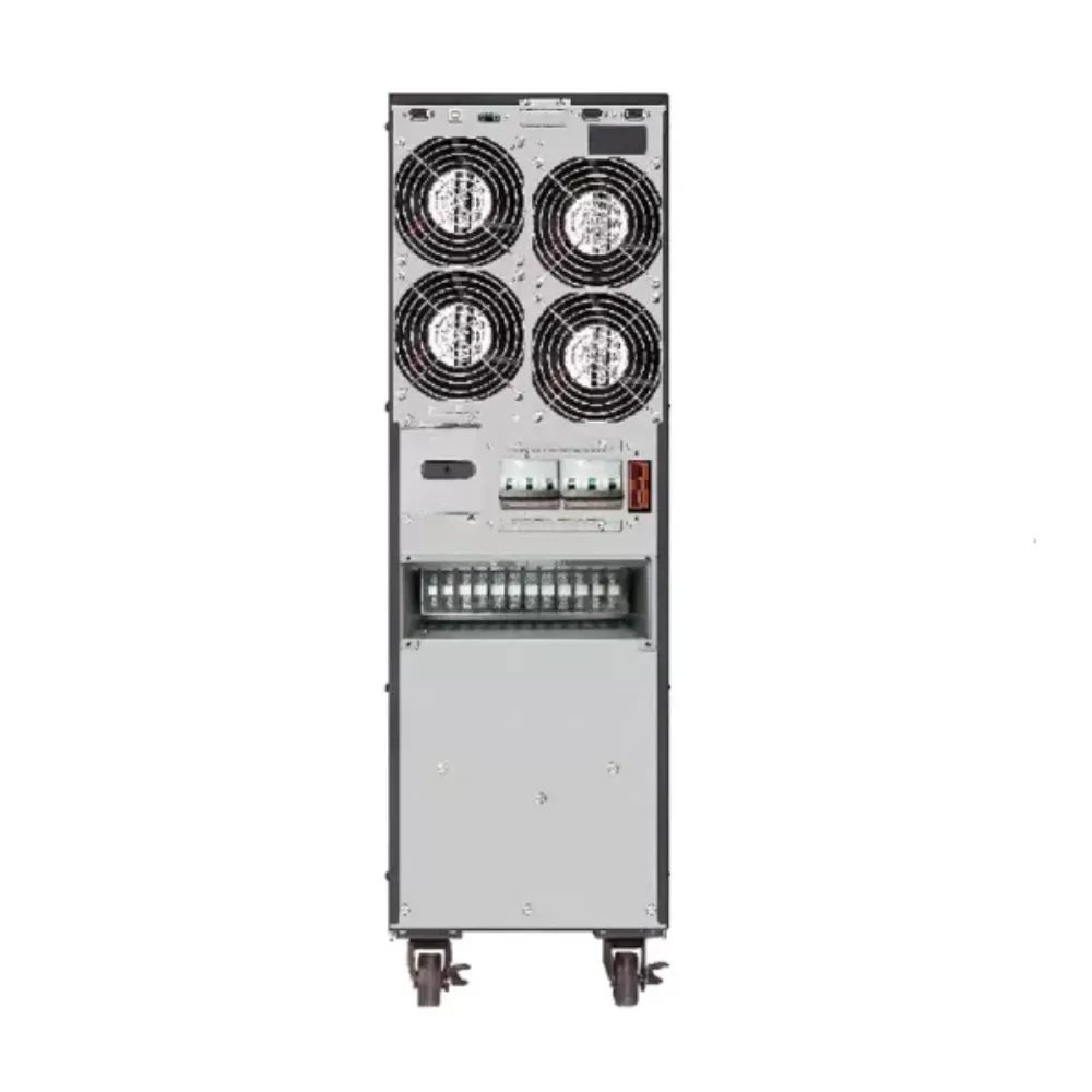
For an isolation transformer in UPS enquiry, send the supplier the UPS model and version, the intended load, existing single-line diagram, available sources, and the separation objective. Add environmental and access constraints, acceptable interruption, and service requirements.
Request the following supporting material:
- A complete drawing identifying main input, separate bypass, batteries, output, and maintenance bypass.
- Transformer location, winding arrangement, ratio, rating, and intended function.
- A mode-by-mode explanation of the required separation boundary.
- Losses, heat, inrush, protection, space, mass, and maintenance information.
- Model-applicable declarations, test evidence, and installation instructions.
- An itemized quotation identifying options, exclusions, and design responsibilities.
A UPS isolation transformer option can be useful without being necessary in every system. Keep open questions visible until the proposed design answers them. If the supplier offers an alternative way to meet the requirement, compare its documents against the same objective.
Keep standards claims specific
The IEC 62040-1:2017 public scope describes a UPS product safety standard and manufacturer-prescribed installation, operation, and maintenance. That summary alone cannot establish a universal transformer requirement for every medical, industrial, or data-center installation.
For an isolation transformer in UPS compliance discussion, request the applicable standard, edition, clause, jurisdiction, and equipment or installation scope. Obtain the relevant documentation and professional assessment. Do not treat a standard’s title, a company certificate, or a general application label as a completed compliance review.
For the broader equipment decision, use the industrial UPS selection guide. For architecture trade-offs, use the low frequency vs high frequency comparison. This page focuses on separation objectives and power paths.
Questions to resolve before approving a configuration
Does every UPS need an isolation transformer?
Do not assume so. Define the required separation, relevant operating paths, applicable requirements, and the selected model’s capabilities. An isolation transformer in UPS design should address a specific documented need rather than a universal rule.
Does double conversion provide galvanic isolation?
Double conversion describes power conversion, not proof of a galvanic barrier. Request the circuit and transformer arrangement. Check other supply paths as well as the normal inverter path before accepting an isolation claim.
Will a transformer regulate voltage and remove all noise?
Do not assume automatic regulation or complete interference removal. Ask for the function and tested performance of the proposed design. Separate voltage conversion, regulation, shielding, and disturbance mitigation in the specification.
Should the transformer be at the input or output?
The correct location depends on the objective and complete circuit. Include separate bypass and maintenance paths in the comparison. Ask the designer to show where the required boundary exists in each relevant operating mode.
Can it improve overload capacity or guarantee longer life?
No general improvement follows from adding a transformer. Verify the complete system’s ratings and request evidence for any reliability or life claim. Include the transformer’s own heat, inrush, space, and maintenance effects in the assessment.
Choose an isolation transformer in UPS design by its documented purpose, location, mode coverage, and installation limits. Keep it separate from claims about universal regulation, guaranteed savings, or automatic compliance.
Prepare a focused enquiry. Send the model, drawing, load details, and isolation objective through Banatton’s contact page. Ask for a configuration and evidence package that addresses those requirements.