 26Sep

A modular UPS system uses replaceable building blocks to provide uninterruptible power supply (UPS) functions. Power modules share the load inside a frame, while controls, bypass, batteries, and distribution complete the system. Which parts are modular or shared depends on the design.
The main buying question is how much protected capacity remains during growth, a module failure, or maintenance. Adding modules can increase capacity. Providing redundancy requires spare supported capacity for a defined operating state.
A modular UPS system can suit a growing server room, commercial facility, or data center. Its value depends on frame limits, service access, battery provision, and the load it must protect. This guide explains those checks so you can compare proposals on the same basis.
Modular UPS system architecture and shared components
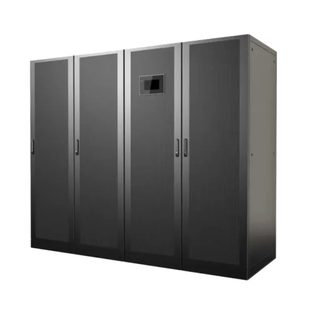
Start by separating a function from a physical module. A rectifier converts AC input to DC. An inverter converts DC to AC for the load.
A power module may contain both, alongside other circuits. A list of seven electrical functions does not prove there are seven parts that can each be replaced on their own.
Schneider Electric’s modular UPS definition identifies power, intelligence, bypass, battery, and distribution modules. It also explains that modular designs differ. Some offer additional controllers or service features; these are model capabilities, not automatic results of modular construction.
For each modular UPS system, ask the supplier to show what is shared and what a single component failure can affect.
| Part | Main role | Question to ask |
|---|---|---|
| Power module | Converts power and carries a share of the load | What capacity remains if one module is unavailable? |
| Frame and busbars | Support modules and carry system current | What are the electrical and slot limits? |
| Controls and communications | Coordinate operation, sharing and alarms | Are controllers redundant, and how does a failure behave? |
| Static bypass | Provides an alternate supply path under specified conditions | Is it shared or distributed, and what is its rating? |
| Battery system | Supplies stored energy during an input outage | Is storage shared, separately protected or modular? |
| Output distribution | Feeds the protected equipment | Which devices or circuits remain common to all modules? |
Define the protection boundary
Several power modules can reduce dependence on one conversion module. They do not by themselves remove shared risks in the frame, bypass, controls, battery, input supply, or downstream distribution.
A modular UPS system with internal N+1 capacity is also different from a 2N arrangement with two complete capacity paths. Even two paths require a review of any common supply, switching, or load connection. State the failure you need the design to tolerate before selecting hardware.
Use the industrial UPS selection guide to check the wider operating environment. Temperature, dust, ventilation, service space, and load behavior still matter when the conversion equipment is modular.
Modular UPS system capacity: growth versus N+1
Keep three figures on the proposal: the frame’s maximum capacity, the capacity currently installed, and the capacity available after the specified failure. Empty module slots do not supply power.
For a modular UPS system using identical modules, installed capacity starts with the number of active modules multiplied by each module’s rating. Frame limits and the maker’s other restrictions still apply. Heat or altitude may reduce the usable rating; this is called derating. Check both real power in kilowatts (kW) and apparent power in kilovolt-amperes (kVA).
Eaton’s modularity overview describes N+1 as having at least one additional module beyond those needed to support the load. The practical check is whether the remaining approved configuration can still carry that load.
Illustrative scenario: four modules do not always mean N+1
Assume four identical 30 kVA/30 kW modules, no derating, and a frame that supports their combined capacity. Installed capacity is 120 kVA/120 kW. If one module becomes unavailable, three remain, providing 90 kVA/90 kW before any further limits.
| Illustrative condition | Installed capacity | Capacity with one module unavailable | Assessment |
|---|---|---|---|
| Load of 80 kVA and 75 kW | 120 kVA / 120 kW | 90 kVA / 90 kW | Within the assumed steady-state capacity limits |
| Load of 115 kVA and 110 kW | 120 kVA / 120 kW | 90 kVA / 90 kW | Exceeds remaining capacity; not N+1 for this load |
These are hypothetical ratings, not a Banatton configuration approval. Phase loading, load steps, overload response, fault isolation, and the battery arrangement still need checking. The example shows why a modular UPS system must be assessed against its protected load.
Preserve the margin as the load grows
A project can lose N+1 capacity without any hardware failure: the load can grow until it needs every installed module. Monitor demand and set an expansion trigger before the required reserve disappears.
For a modular UPS system, also confirm whether the next module fits the existing frame and approved configuration. Extra slots are useful only if the input, bypass, output, cooling, protection, and battery system can support the planned state.
The 50 kVA, 100 kVA and 200 kVA capacity guide provides a starting point for discussing those project sizes. Request the actual module combination and remaining capacity rather than relying on the frame label alone.
Planning staged growth? Send Banatton your present load, future load and redundancy target so the configuration review can cover each stage.
Modular UPS system maintenance and bypass paths
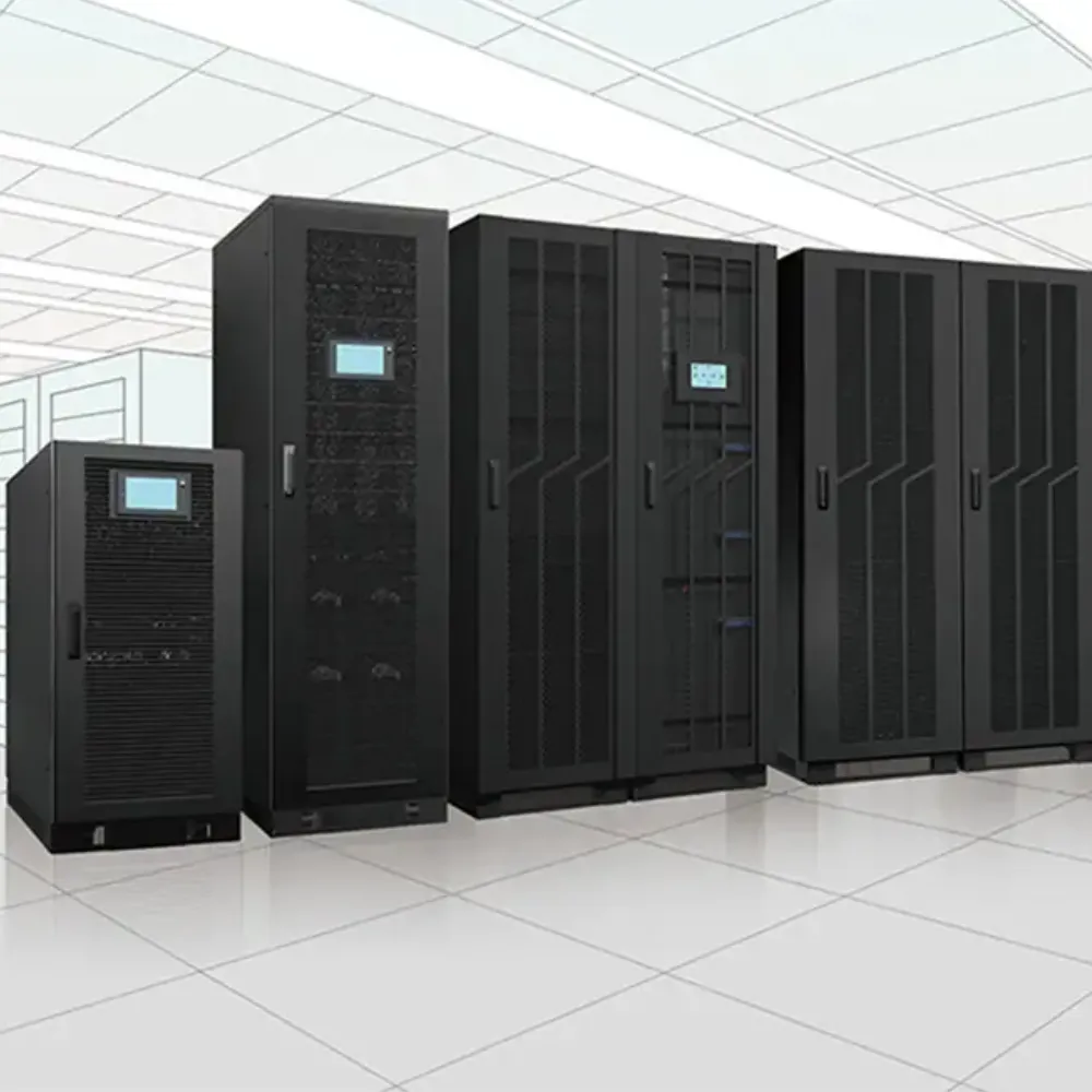
Hot-swappable describes a supported service capability under defined conditions. It does not mean any part can be removed in any operating state. Check the exact component, permitted load, available supply, procedure, and service requirements.
Before specifying a modular UPS system for maintenance without a load shutdown, ask what happens to the load while each service task takes place. Replacing a power module may have different conditions from servicing a shared bypass, controller, battery circuit, or frame connection.
Know which path supplies the load
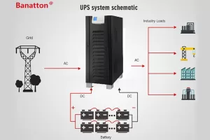
In normal online double-conversion operation, the rectifier and inverter form the conversion path. During an input outage, an approved battery system supplies energy to the inverter. A static bypass provides another path when its transfer conditions are met.
A maintenance bypass allows service isolation according to the system design. The load may remain energized, but that does not establish that it retains inverter conditioning or battery backup.
Schneider Electric’s bypass explanation distinguishes static and maintenance bypass and describes the loss of battery backup on the maintenance bypass path. Apply the selected manufacturer’s own operating instructions to the proposed installation.
Illustrative scenario: a module service window
A facilities team has a hypothetical four-module installation serving a load within the capacity of three modules. It wants to remove one module for planned service. The remaining steady-state capacity is only the first check.
The team also confirms the permitted service mode, current alarms, replacement compatibility, and the approved isolation procedure. While one module is out, the spare-module margin may be consumed. Another failure during that window could exceed the intended protection level.
This modular UPS system review turns easy maintenance into a defined operating plan. It does not promise that every service task avoids bypass or a planned interruption.
Backfeed protection is another item to verify in the design. Its purpose includes preventing UPS-side energy from creating hazardous voltage at input isolation points. It is not protection against ordinary utility power entering the rectifier. Confirm the required arrangement in the equipment installation manual; it is not a substitute for the service isolation procedure.
Need a specific maintenance state supported? Ask Banatton to review the load and service requirements, including which component must be unavailable and what protection must remain.
Efficiency, battery runtime and lifecycle cost
Compare efficiency at the expected load and operating mode. A large frame with few modules installed can operate differently from a fully populated frame. The relevant question is how the proposed configuration behaves across your load profile.
Some designs support module sleep or rotation strategies. For a modular UPS system with that feature, confirm how many modules remain active, how wake-up works, and how the required redundancy is maintained. Do not assume that fewer active modules always improve the complete system’s protection or efficiency.
Treat battery capacity as a separate requirement
Power modules establish conversion capacity. Batteries establish an energy resource with their own limits. Adding a power module does not automatically add battery runtime.
Check backup minutes at the critical load, approved battery voltage and chemistry, discharge conditions, charger capacity, and the required recharge window. Also ask whether a battery fault or battery service task affects all power modules or only part of the system.
For a modular UPS system, separate one spare power module from redundant battery capacity. The two statements do not describe the same failure tolerance.
Compare complete installed costs
Include the frame, initial modules, future modules, batteries, switchgear, installation, cooling, monitoring, spares, and service. Allow for access and replacement work, not just cabinet footprint.
An incremental purchase plan can defer some equipment spending, but future module availability and compatibility matter. Confirm the supported product lifecycle and expansion arrangements before relying on a long-term buildout plan.
A modular UPS system can offer practical growth and service benefits. Savings still require a comparison with an alternative that meets the same load, runtime, redundancy, and maintenance goals. Avoid applying a fixed savings percentage without a project-specific calculation.
Compare modular and conventional configurations
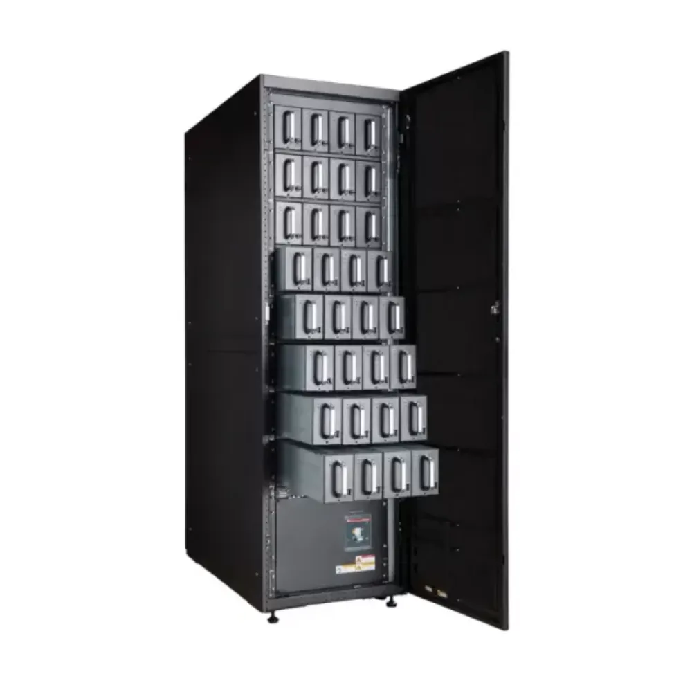
A conventional UPS can be suitable where demand is stable and the service plan fits the site’s operating needs. A modular design can be useful when smaller expansion steps or replaceable power sections have value.
Neither approach removes the need to design the surrounding electrical system. Compare the approved configurations, rather than assuming that modular construction guarantees higher reliability or that a conventional UPS cannot support redundancy.
Illustrative scenario: stable demand or phased expansion
One office has a steady protected load and a planned shutdown window for service. Another expects several equipment additions and needs a defined module-removal state supported during business hours.
The first team compares a fixed configuration with its service plan. The second checks staged module additions and remaining capacity at each stage. Both include battery and distribution requirements. Their modular UPS system decisions can differ even when the present loads are similar.
For a conventional three-phase product comparison, review the BT900-33 online UPS family. It is a separate product family; its parallel-unit limits and battery specifications must not be applied to BT9300-M modules.
Consider the full Banatton UPS systems range when choosing which architecture to investigate. Keep the comparison tied to measured demand, available infrastructure, and service expectations.
Review a Banatton configuration and common questions
Use the modular UPS category to begin a product discussion. The BT9300-M product page lists a three-phase modular family with different frame and module options.
For the BT9300-M column, the public table lists a 30–300 kVA/30–300 kW cabinet range and a maximum of 10 power modules. Confirm the supported module rating and configuration in the current datasheet. Frame maximum capacity does not establish usable N+1 capacity.
The BT9300-M data center guide expands the model discussion. For a modular UPS system quote, request the frame, module count, bypass, battery plan, and service limits together.
The public product page gives efficiency figures in both feature text and a technical table without a common set of stated test conditions. Use a current, configuration-specific efficiency curve for procurement rather than treating a headline value as a guarantee at every load.
Does modular construction eliminate single points of failure?
No. Power-module redundancy can address a defined module outage, while shared controls, bypass, busbars, batteries, or distribution may remain. Review the protection boundary of the complete modular UPS system.
Can every module be replaced while the load stays on?
That depends on the component and approved service procedure. Confirm whether the task uses the inverter path, bypass, or a planned interruption. A hot-swap claim for power modules does not automatically cover every other component.
Does adding one module create N+1 redundancy?
Only if the remaining approved capacity can support the required load after the specified module becomes unavailable. Check both kW and kVA, derating, phase loading, and dynamic limits. Installed capacity alone is not proof.
Does adding power capacity extend battery runtime?
Not by itself. Battery runtime must be checked for the actual load and approved battery configuration. A modular UPS system may need additional battery or charging provision as demand grows.
Check the proposal against each operating state
Before approving a modular UPS system, ask for a short schedule covering these states:
- Normal load with all required modules active.
- Peak load with one power module unavailable.
- Planned module service with the agreed protection level.
- Battery operation at the required critical load.
- Future load after the next equipment addition.
List the available kW and kVA beside each state. Record which parts are shared and which limits still need confirmation. This makes two modular UPS system proposals easier to compare without relying on a frame rating or a general hot-swap claim.
What should be included in a configuration request?
Provide input and output voltage and phase, normal and peak kW/kVA, expected growth, required runtime, and the failure or service state to be supported. Include generator and bypass details, environmental conditions, and space for equipment and maintenance.
Request a project review: Contact Banatton with your load schedule and operating requirements. Use that information to select a modular UPS system with a documented capacity, battery, bypass, expansion, and maintenance plan.