 26Sep

A battery management system (BMS) monitors battery cells and helps keep them within safe limits. It can balance cells, report limits, and trigger protective action. The exact functions vary, and the connected charger, uninterruptible power supply (UPS), or inverter must respond correctly.
A battery can hold enough energy yet fail to power your equipment. A current limit, a cell condition, or an unsupported control interface may be the cause.
Consider Alex, a fictional facility manager reviewing a battery for a 2 kW AC load. They compare the energy rating, then check the battery’s permitted current. A nominal-voltage estimate looks acceptable, but a lower-voltage calculation exceeds the assumed limit.
Alex pauses the shortlist and requests the operating data before selecting equipment. The worked example explains that decision.
This guide explains how the controls work, why their limits matter, and which records show that the equipment can work together. You’ll get a supplier checklist for UPS and fixed storage projects. You don’t need to design the circuits to ask the right questions.
Key Takeaways
- Cell-level measurements can reveal a limit that the total pack voltage does not show.
- State of charge is an estimate; it does not establish available energy or backup runtime by itself.
- Cell balancing manages charge differences and cannot restore permanently lost cell capacity.
- Matching CAN or RS485 labels does not prove that a battery and inverter can exchange the required messages.
- Check supported equipment, current limits, firmware, fault response, and restart conditions before approving a configuration.
What is a battery management system?
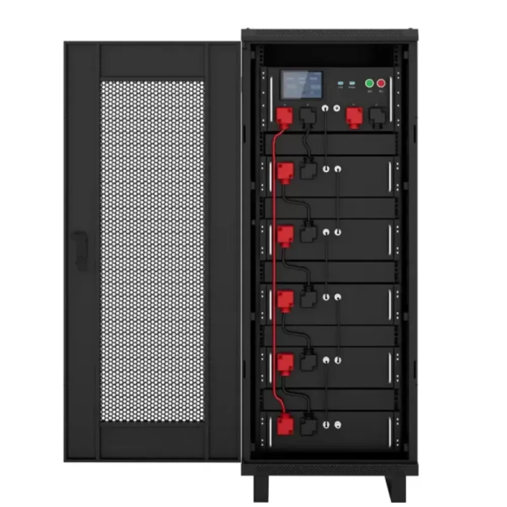
A battery management system uses circuits and software to oversee a battery that can be recharged. It may track voltage, current, and heat, estimate charge, balance cells, and limit charging or discharge. These functions help keep each cell within the limits set for its intended use.
A cell is a single unit that stores and releases energy through chemical reactions. A module groups cells.
A pack combines cells or modules with wiring and other parts. The battery management system may track each cell, each module, or more than one level in a large pack.
You’ll find BMS technology in electric vehicles, small devices, factory equipment, and fixed storage. This guide focuses on lithium batteries used with backup power and inverters. Lead-acid batteries also use monitoring systems, but their controls and charging needs differ.
Start with Banatton Group’s storage battery selection guide to define the duty, chemistry, and energy your project needs.
Separate management from monitoring and charging
A device’s name doesn’t tell you all it can do. Check the functions in its manual:
| Device or system | Main responsibility | Buyer check |
|---|---|---|
| Battery monitoring system | Measures and reports battery conditions | Does it only report, or also control equipment? |
| BMS | Supervises battery limits and configured functions | Which measurements, estimates, protection, and balancing are included? |
| Charger | Supplies charging power under its control settings | Can it follow the battery’s permitted voltage and current? |
| Energy management system (EMS) | Coordinates wider energy use and scheduling | Does its dispatch respect the battery’s limits? |
A battery monitoring system may raise alarms but have no way to control charging or open the battery circuit. An EMS plans when energy is used. That doesn’t make an unsupported battery pairing work. Here, BMS means battery management, rather than building management.
How a battery management system works
The basic steps are measure, estimate, decide, and act. A battery management system reads sensor signals and checks them against set limits. It then sends messages or controls hardware.
Not every product has every function. Some protection circuits can act on their own, apart from the main software.
Measure voltage, current, and temperature
A total pack reading can hide a cell that is near its voltage limit. That’s why cell-level readings matter. Current sensors track how fast charge enters or leaves the pack. Temperature sensors check whether it is too hot or too cold to work within its stated limits.
A lithium battery management system must use limits that suit its cell chemistry and pack design. The allowed current and temperature may differ for charging and discharge. Don’t copy settings from another battery just because both carry a lithium label.
Measuring temperature doesn’t cool a pack. Some designs can request less power, switch a fan or heater, or stop the battery. A sensor alone doesn’t prove that heating or active cooling is built in.
Estimate charge and act on limits
State of charge (SoC) is an estimate of the charge left, compared with a defined full-charge value. A controller may use current, voltage, and a model of the battery to work it out. Coulomb counting adds up measured current over time to track the change in charge. Errors in the readings or starting value affect the result.
For example, take 40 Ah from a defined 100 Ah reference. Under ideal assumptions, that is a 40-percentage-point change in charge. It doesn’t prove that an old battery still holds 100 Ah.
State of health (SoH) describes its condition. It may reflect how much capacity remains or other measures set by its maker.
Use the battery capacity calculation guide to separate charge in Ah from energy in Wh. Neither a charge percentage nor an Ah label gives the complete runtime answer.
The battery management system may ask for less charge or discharge current before protection opens the circuit. Orion’s explanation of its BMS shows who must act: the source and load receive current limits and must respect them.
Battery management system balancing and types
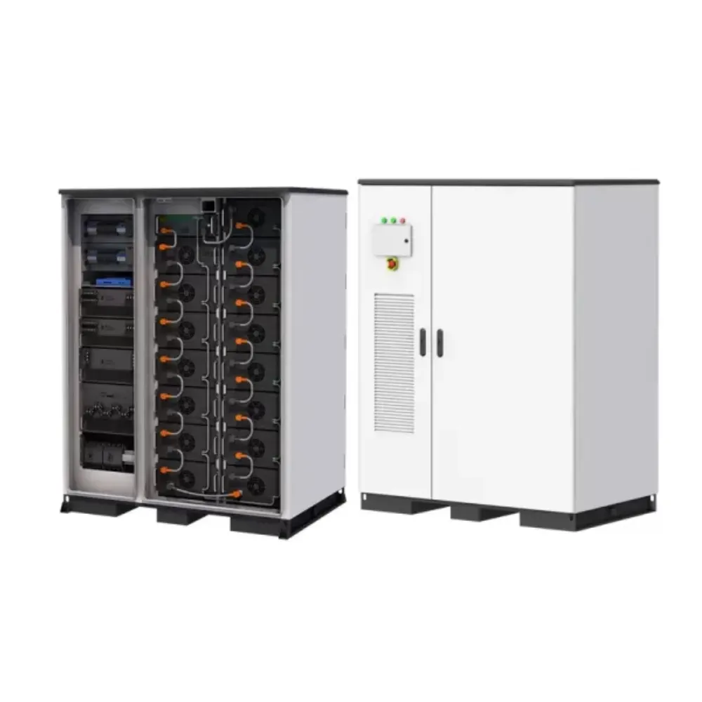
Cell balancing helps manage charge differences between cells. In a series string, cells share the same path for current. One cell that reaches its limit can restrict the charge the whole group can use. Balancing helps with that mismatch.
It can’t repair a faulty cell or restore capacity that is permanently lost.
Compare passive and active balancing
Analog Devices’ cell-balancing explanation describes two ways to handle excess charge: release its energy as heat, or move charge within the pack. Each needs different hardware.
| Approach | What happens to excess charge | Practical consideration |
|---|---|---|
| Passive cell balancing | A controlled resistor dissipates energy as heat | Check balancing current, heat, and the conditions when balancing operates. |
| Active cell balancing | Additional circuitry transfers charge within the battery system | Check transfer capability, control conditions, complexity, and service requirements. |
Neither method proves the quality of the whole battery management system. Ask how cell balancing works in the quoted pack and when it can run. A larger balancing current alone doesn’t prove longer life or more backup time.
Similar cell voltages don’t give a full health check. Cells may still differ in capacity or resistance. Their voltages can look alike at one point even when their condition differs.
Compare common control architectures
Ansys describes several BMS architectures, including centralized, modular, primary/subordinate, and distributed designs. The categories can overlap; there is no single universal count of types.
- Centralized: one control assembly connects to the monitored cells. The wiring and connector arrangement matters as the pack grows.
- Modular: repeated monitoring or control units supervise portions of the battery, with coordination across the assembly.
- Distributed: electronics sit near cells or modules and communicate across the system.
- Primary/subordinate: subordinate units report measurements while a primary controller handles coordination and external communication.
Choose a battery management system layout that suits the pack size, service access, and control needs. The layout alone doesn’t show whether it supports a given inverter.
Match the BMS to the UPS or inverter
BMS compatibility means the electrical limits, controls, and supported equipment must fit together. Start with the exact battery, charger, and UPS or inverter models. The nominal voltage is a named reference value. Matching it is only one check.
Check current at the operating voltage
Return to Alex’s hypothetical 2 kW load. Assume a 48 V battery and 90% inverter efficiency, held constant for this simple example. The approximate battery current is:
DC current ≈ AC load watts / (battery voltage × inverter efficiency)
| Assumed operating point | Calculation | Approximate current |
|---|---|---|
| 48 V battery voltage | 2,000 / (48 × 0.90) | 46.3 A |
| 42 V battery voltage | 2,000 / (42 × 0.90) | 52.9 A |
Assume the allowed continuous current is 50 A. The second point exceeds it. Alex can’t approve the pairing from the nominal-voltage sum alone. They ask for the allowed voltage range, steady and peak current limits, and efficiency data for the intended load.
These are teaching assumptions, not a battery recommendation. The 42 V point is not a proposed cutoff. The 90% value is not a Banatton efficiency claim. To select equipment, also check the supported pairing, temperature, length of any surge, and other losses.
A lithium battery management system can limit current even when the pack holds plenty of energy. More Ah won’t always solve that problem. If you are changing chemistry, review the separate lithium-ion versus lead-acid UPS battery comparison before treating a replacement as compatible.
Verify messages, firmware, and fault response
CAN and RS485 labels describe data-link technologies. They don’t show that two devices understand the same messages. Check the protocol, or rules for those messages. The settings, wiring, and firmware must also match the supported equipment pairing.
For example, Victron’s GX connection guidance lists 250 and 500 kbit/s profiles and points buyers to its supported battery list. Those rules apply to the stated Victron equipment. They show why a shared connector doesn’t prove a match.
Consider Jordan, a fictional solar integrator comparing a battery and inverter that both list CAN. They have two brochures, but no record that the exact models and firmware work together.
Jordan asks for that record and the stated response if the data link fails. They keep the purchase on hold until the supplier confirms the supported pairing. The port label alone isn’t enough to approve it.
Use this checklist when requesting a battery and power-system proposal. Ask the supplier to complete it for the quoted equipment, including any limits or unresolved conditions.
| Record to request | What it should establish |
|---|---|
| Exact models, chemistry, and battery arrangement | The supported battery, charger, and UPS/inverter combination. |
| Operating voltage and charge/discharge limits | The conditions under which the equipment may operate together. |
| Continuous and peak current, with duration | Capability at the required load, temperature, and operating voltage. |
| Interface, application protocol, pinout document, and firmware revisions | A documented communication path for the quoted versions. |
| Handling of reported current and voltage limits | How the charger and load act on changing battery limits. |
| Cell-voltage, temperature, and communication faults | Alarm, power reduction, interruption, and critical-load effects. |
| Shutdown and restart conditions | Recovery behavior and who may authorize or perform it. |
| Manuals, approved commissioning record, test method, and applicable compliance evidence | The acceptance basis for the complete configuration. |
The checklist supports procurement and engineering review. It does not replace the manufacturer’s installation instructions or an approved commissioning procedure.
Read BMS alarms and safety limits correctly
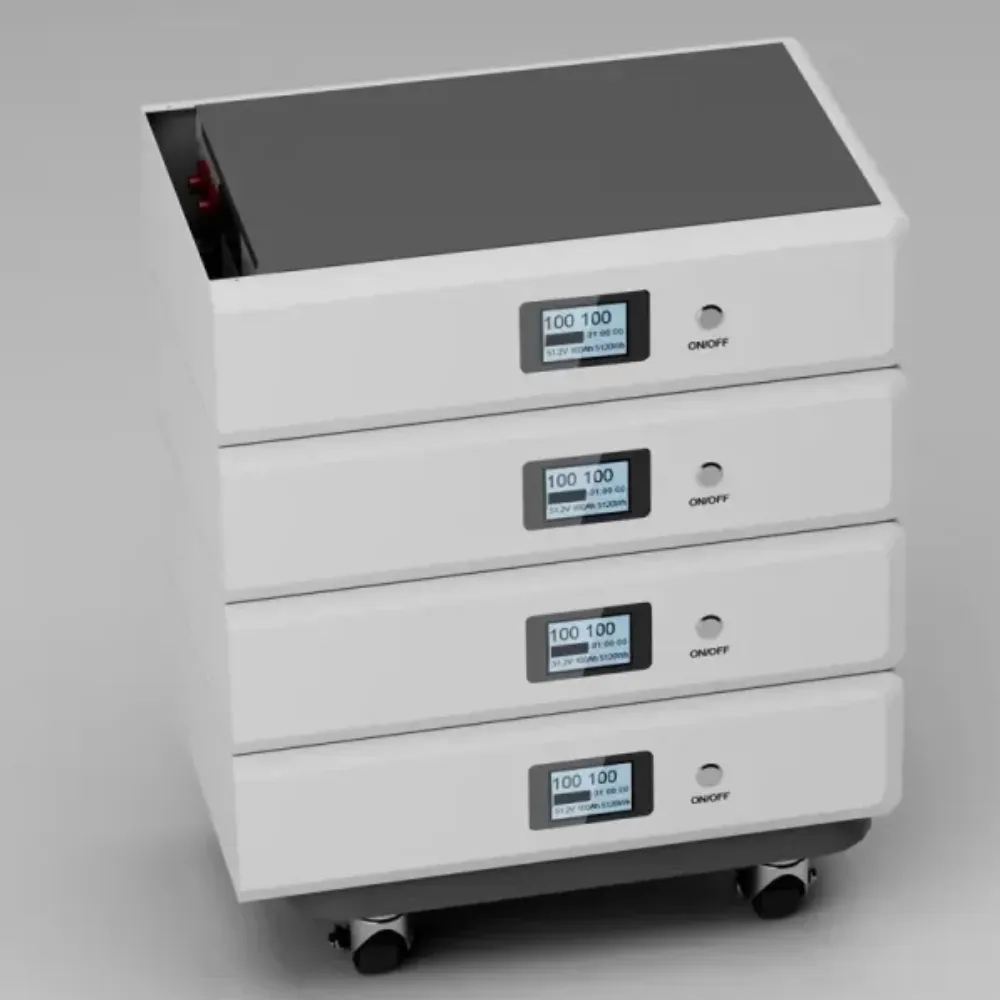
A battery management system alarm tells you about a condition that needs checking. It doesn’t give a full diagnosis. A normal-looking screen also doesn’t guarantee that backup power is ready.
Separate charge, health, and runtime
Four questions deserve separate answers:
- How much charge does the controller estimate remains?
- How much usable capacity does the battery retain?
- How much power may it deliver under the present conditions?
- How long can the approved system support the actual load?
A battery can show a high state of charge but supply less power because it is too hot, too cold, or at another limit. An old battery may reach full charge yet hold less energy than when new. Check what the battery management system’s displayed values mean. Ask whether its estimates need a calibration process set by the maker.
Use UPS runtime calculation with discharge data for the load-and-duration question. A runtime display or rough energy sum serves a different purpose from discharge data tested for the stated battery and load.
Plan interruption and recovery
Protective action can cut power to the load. Check what the UPS or inverter does if the allowed current falls, the battery disconnects, or the data link fails. Some faults may cause shutdown without a warning period.
Keep the fault code, conditions at the time, and the equipment’s stated response in the service file. Some systems restart on their own. Others need another device or authorized service staff to act.
Repeated resets can hide a problem if no one addresses the cause.
The battery management system is one part of the safety design. You still need the required electrical protection, skilled installation, checks, and a safety review of the whole system. Follow the exact manuals. Don’t bypass protection to keep the load running.
Battery management system questions
How does a BMS work?
A BMS reads battery conditions, checks them against set limits, and sends messages or acts on the circuit. It may estimate charge, balance cells, and stop charging or discharge. Check which functions the selected product includes.
What are the main types of BMS?
Common layouts include centralized, modular, distributed, and primary/subordinate designs. Sources group them in different ways.
Choose a layout for the pack design, control needs, and ease of service. Don’t assume there is one fixed number of types.
Is a BMS the same as a battery monitoring system?
A battery monitoring system measures and reports conditions. Management may add control, protection, and balancing. Product names can overlap, so read the list of functions. The label alone doesn’t tell you what the device can do.
Does a BMS replace the charger?
No. The charger supplies charging power. Battery controls can send limits or restrict charging through built-in protection. Check that the charger follows the right settings and control method for that battery.
Can any CAN or RS485 inverter work with my battery?
No. BMS compatibility depends on supported models, message protocol, settings, firmware, and the stated connection. A matching port label doesn’t prove the devices can work together. An adapter alone doesn’t prove an approved pairing either.
Can a BMS damage a battery or guarantee its service life?
Wrong settings, failed parts, or a poor equipment match can weaken battery protection. A system chosen and set up correctly helps manage limits. It can’t guarantee service life in all conditions. Follow the actual battery instructions for charging and care.
Specify the battery and controls together
Choose a battery management system as part of a complete equipment setup. Start with the load you need to protect and how long it must run. Then check the battery’s allowed current across its range of use. Keep charge level, remaining capacity, power, and backup time as separate checks.
Before you accept a proposal, record the exact models and firmware. Ask how the charger and inverter respond to changing limits. Find out what happens if the data link fails and how the system restarts after a fault.
Keep the answers with the manuals and setup test records. Service staff will need them later.
Banatton Group supplies battery and power equipment for project inquiries. Check each battery management system need against the exact products in the proposal.
Request a battery and power-system quote with your load, runtime, site temperature range, existing UPS or inverter model, and interface needs. Ask for the supported equipment pairing and its operating records. Your team can then review battery management system limits alongside energy and power needs.