 26Sep

Voltage stabilizer maintenance means checking the unit’s external condition, keeping records, and arranging service as its model manual requires. Qualified personnel must handle internal cleaning, brush checks, and electrical tests using the manual and the site’s isolation procedure.
A date on the calendar is only useful if the work matches the equipment. A relay stabilizer, a servo unit, and an electronic regulator can sit in the same room but need different checks. Even two servo units may differ in cooling, load, and service needs.
For a site team, the key questions are who checks what, when the unit needs a planned shutdown, and who acts on the findings. This guide gives you a routine checklist, a way to set service dates, and a record template. It covers standalone mains voltage stabilizers. Generator excitation regulators, which may also be called automatic voltage regulators, have a different scope.
Key takeaways
- Use the exact model manual to set service intervals, inspection methods, and replacement limits.
- Keep operator observations outside the enclosure; assign internal work and electrical tests to qualified personnel.
- Servo brush inspections apply to equipment with that mechanism. Oil checks apply only to oil-filled units.
- Bypass position alone does not prove electrical isolation. Record the task owner, findings, and next action after each visit.
Match maintenance to your stabilizer type
Identify the regulating mechanism
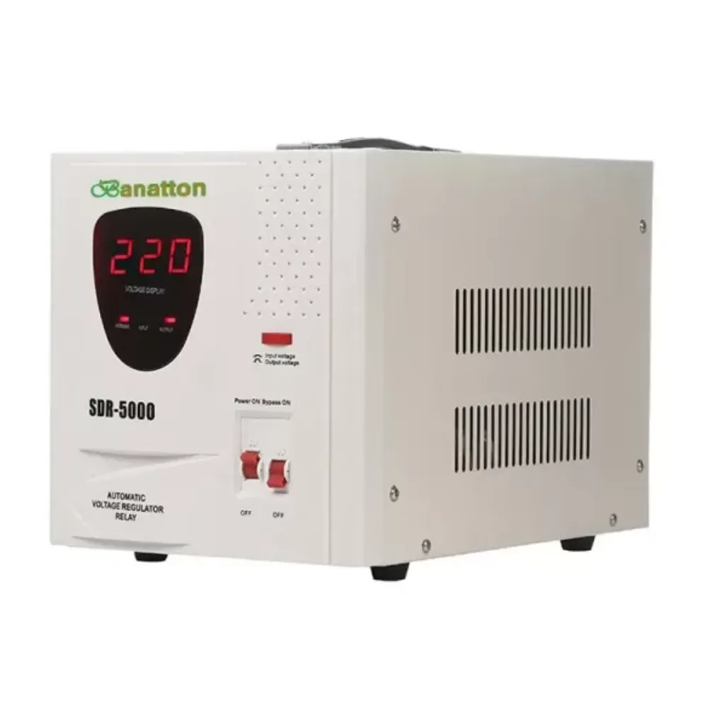
Start with the nameplate, model documentation, and installation records. The cabinet’s appearance is not enough to identify its internal design. If the mechanism is unclear, request the relevant manual before adding internal tasks to a checklist.
| Stabilizer design | Maintenance concerns | Scope to confirm in the model manual |
|---|---|---|
| Servo with a motor-driven regulating brush | Brush and track condition, drive movement, and cooling | Correct brush part, wear limit, inspection method, and permitted mechanical servicing |
| Relay or tap-switching design | Switching contacts, control components, connections, and heat | Contact inspection criteria, protective functions, and approved replacement parts |
| Static or electronic regulation | Power electronics, cooling, connections, and any fitted filters or fans | Cooling requirements, fault records, and authorized diagnostic procedures |
These are planning distinctions. A static design can still contain contactors or fans, and a servo system may have several separate brush assemblies. Avoid treating a general technology label as a complete parts list.
Banatton Group’s voltage stabilizer range includes relay and servo categories. Use the category to identify the relevant product family, then confirm maintenance requirements against the exact model.
Check cooling and installation details
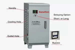
Record whether the equipment is air-cooled or oil-cooled. Note its ventilation clearances, permitted ambient conditions, and any installed bypass arrangement. Oil sampling, gasket checks, and leak assessment belong only on the scope for equipment that actually uses oil.
Keep the current manual revision with the asset record. If the load or supply arrangement has changed, review suitability separately; Banatton’s voltage stabilizer selection guide explains the types and sizing questions to resolve.
Use a routine voltage stabilizer maintenance checklist
Observe external condition and existing displays
Routine checks help operators report changes without entering the equipment. Set the observation frequency through the site’s operating procedure and manufacturer guidance. Complete the following checks only from a safe, normal operating position.
| Check | What the operator records | When to refer the finding |
|---|---|---|
| Enclosure and surroundings | Visible damage, moisture nearby, or objects obstructing access | Damage, water ingress, or unsafe access needs prompt assessment |
| Ventilation | Visible dust accumulation or blocked external airflow paths | Report obstruction or unusual heat indications; do not reach through vents |
| Status display | Existing input/output indications, load indication, and alarm text, where fitted | Report new alarms, changes from usual operation, or missing indications |
| Sound and odor | A change noticed during normal rounds | Report burning smells, arcing sounds, or persistent abnormal noise immediately |
| Operating history | Recent trips, supply interruptions, and changes to connected equipment | Pass repeated events or material load changes to the responsible service team |
Copy the labels as well as the numbers. On a three-phase unit, note the phase and whether the display shows line-to-line or line-to-neutral voltage, if labelled. Include the units. This helps the service team compare like with like.
A panel reading alone cannot show that the unit meets its rated output limits. Load and supply conditions matter too. The service team can decide whether to make further measurements or run a controlled test.
Keep cleaning within the authorized scope
Check the manual before wiping or vacuuming the exterior, including any required shutdown conditions. Do not spray liquid into vents, cover a running unit, or remove its casing to reach accumulated dust. Internal cleaning methods depend on the components and construction.
Illustrative example: Alex, a fictional workshop supervisor, notices dust building up around a stabilizer after a nearby process changes. They record the location and alert the maintenance planner without opening the cabinet. The planner checks the model’s cleaning instructions and asks the service team to review the interval. The result is a defined service task rather than an improvised cleaning job.
Plan voltage stabilizer servicing with qualified personnel

Establish isolation before internal work
A bypass may keep the load supplied through a different power path. Its position alone cannot show that every part of the stabilizer is safe to touch.
Before internal work, the qualified service team must identify each energy source and isolation point. Backfeed means power can reach the unit from another source. Stored energy may also remain after a supply is off. The team must follow the manual and site procedures to establish and verify a safe condition.
For US workplaces, OSHA 29 CFR 1910.333 addresses deenergization, isolation, lockout/tagout, and qualified verification of absence of voltage. Its verification provisions include possible induced voltage or backfeed. Outside the US, use the applicable local requirements and site procedures.
Do not use a dark display, a stopped fan, or a fixed waiting period as proof of isolation. A general maintenance checklist cannot specify the switching sequence for an unknown installation.
Agree the inspection and test scope
Qualified technicians should build the work scope from the model’s service instructions and prior findings. Depending on the design, it may include:
- Regulating brush, contact track, and mechanical drive inspection on applicable servo units
- Relay, contactor, terminal, and wiring condition checks
- Cooling fan, filter, and airflow inspection where fitted
- Oil-system inspection and specified testing on applicable oil-cooled equipment
- Appropriate output-regulation, alarm, and protective-function tests
For servo stabilizer maintenance, check the regulating brush’s part number and wear limit. Age alone is not a replacement rule. Keep it distinct from any motor brush, which may have different service needs.
Use the stated method and torque for each connection. Before adding lubricant, confirm which part needs it, what to use, and how to apply it. Insulation tests need an approved procedure that protects sensitive electronics. That may require parts of the unit to be disconnected before testing.
The HPCS operation instruction manual, assigns repair and maintenance to qualified technicians. It also requires input disconnection and no current or voltage inside before servicing. These are instructions for the equipment covered by that manual, rather than a Banatton service procedure.
Set a voltage stabilizer maintenance schedule
Start with the equipment manual
There is no single service interval that fits every stabilizer. Separate routine observations from planned internal servicing and from replacement limits for individual components.
Different sources illustrate why scope matters. Section 4 of the ATO three-phase voltage stabilizer manual, recommends maintenance at intervals no longer than three months for its covered equipment. It notes that maintenance cycles differ with the operating environment.
By comparison, Sinalda’s general maintenance guidance suggests annual maintenance, potentially every six months in harsh or demanding conditions, while directing readers to manufacturer instructions.
Those recommendations apply to different scopes. Neither establishes a universal schedule for a Banatton unit. Start with the installed model’s documentation and have the responsible service team resolve gaps before setting a due date.
Review conditions and previous findings
A useful schedule records why each task is due. Dust exposure, heat, operating hours, load changes, and previous wear findings can justify review. An abnormal event may require assessment before the next planned visit.
| Planning trigger | Task to arrange | Responsible role | Basis for timing |
|---|---|---|---|
| Normal operation | External observations and status records | Operator under site procedure | Manual and site inspection plan |
| Planned service date | Applicable internal inspection and tests | Qualified service personnel | Exact-model instructions and service history |
| Changed dust, heat, load, or duty | Review conditions and service frequency | Maintenance planner with service team | Environmental limits and observed findings |
| Alarm, repeated trip, or suspected damage | Prompt assessment under the incident procedure | Authorized operating and service personnel | Severity and the site’s escalation rules |
| Component reaches its specified limit | Approved replacement and follow-up checks | Qualified service personnel | Model and component criteria |
Illustrative example: Sam, a fictional maintenance planner, manages a relay unit and a servo unit in the same building. They discover both have the same generic work order. Sam separates the records, checks each manual, and assigns brush inspection only to the applicable servo mechanism. Each asset now has its own task list and documented review date, without assuming identical service needs.
If the manual is missing, request it using the model and serial number. A generic online schedule is not a substitute for the correct instructions.
Keep a maintenance log that supports decisions
Use a consistent record template
A useful voltage stabilizer maintenance log links each finding to an action. It should identify the unit, record the conditions at the time, and name who will act next. Include the limits used to judge the work so the next team knows what was checked.
Copy this field structure into your maintenance system or spreadsheet:
| Record field | Information to enter |
|---|---|
| Asset identity | Location, asset ID, manufacturer, model, and serial number |
| Equipment configuration | Relay/servo/electronic design, phase arrangement, cooling type, and relevant installation drawing |
| Instructions | Manual revision and approved task or service-procedure reference |
| Visit details | Date, time, responsible person, role, and reason for the check |
| Operating condition | Running/stopped state, connected equipment, and relevant load or supply changes |
| Existing indications | Displayed values with units, phase references, and alarm text, where available |
| Findings | External observations or technician findings, with photographs where safe and permitted |
| Service record | Work completed, parts used, specified acceptance criteria, and recorded test results |
| Safety and release records | Applicable isolation record reference and authorized return-to-service decision |
| Follow-up | Action owner, next review/service date, and unresolved items |
Operators should complete observation fields within their role. Service and release fields belong to the authorized personnel who perform and assess that work. Refer to the formal isolation record rather than using this general log as an isolation permit.
Describe findings precisely
Compare readings only when the operating conditions and measurement references are understood. If one entry was taken with the load stopped and another during production, record that difference before interpreting a change.
For a hypothetical log entry, “dust visible at external inlet; no enclosure opened; referred to maintenance planner” is more useful than “unit checked.” The follow-up still needs an owner and a decision. Leave measurements blank if none were taken; a completed-looking record is less useful than an honest one.
Before closing a service work order, confirm that unresolved findings have an action owner. Record why the next interval was retained or changed, and reference the person authorized to approve return to service.
Recognize warning signs and prepare a service handoff
Smoke, burning smells, visible arcing, water ingress, or repeated trips require prompt action under the site’s emergency or incident procedure. Keep people away from affected equipment. Do not open the enclosure, repeatedly reset protection, or operate unfamiliar switching equipment to investigate.
When safe, provide the service team with the model and serial number, exact alarm text, event timing, affected load, and recent changes. Include the most recent maintenance record and identify which findings remain unresolved.
For active symptoms such as no output, delayed operation, or load-related trips, use Banatton’s voltage stabilizer troubleshooting guide to organize observations for the service team. Preventive records and incident records should remain connected, so the same issue is not lost between visits.
Voltage stabilizer maintenance FAQs
How often should a voltage stabilizer be serviced?
Follow the installed model’s manual and review the interval against its environment, duty, and previous findings. Manufacturer recommendations differ. Keep routine observation, planned internal service, and component replacement as separate tasks with their own documented basis.
What can an operator check without opening the enclosure?
An operator can record existing display indications, alarms, visible external condition, ventilation obstructions, and changes noticed during normal rounds. Follow the site’s procedure. Internal access, electrical measurements, connection work, and adjustments belong to qualified personnel.
Do all voltage stabilizers have carbon brushes?
No. Servo units with a brush-regulated variable transformer need the applicable brush inspection. Relay and static/electronic regulation use different mechanisms. Confirm the model and components before adding brush work to its service plan.
Does switching to bypass make a stabilizer safe to service?
Bypass position alone does not prove isolation. The actual circuit arrangement, other supply sources, and stored energy must be considered. Qualified personnel must establish and verify the safe condition under the equipment instructions and site procedure.
What should a maintenance log contain?
Record asset identity, date, operating conditions, findings, work completed, applicable limits, and follow-up ownership. Include service and release records from the authorized team. A useful entry explains what changed, what was done, and when the next decision is due.
Good voltage stabilizer maintenance starts with the correct manual and a clear assignment of responsibilities. Use the checklist to observe, the service plan to define qualified work, and the log to carry findings forward. For a Banatton unit, contact Banatton with your model details to request the applicable maintenance documentation or ask about a specific service requirement.